 Broke is the past tense of break, but neither are defined as a defect. Here are a few common causes for valves to break.
When you consider an engine running at full load, this gives a better understanding of the conditions and demands valves must consistently function under. At this rate of speed, temperature, and force it does not take much of an abnormal condition to cause valve failure.
This article focuses on the valve itself and is by no means all encompassing, but here are some common valve failures.
Just to be fair – yes – valves can be defective. Manufacturers can use inferior materials, inadequate he.’lt treat processes, deficient welds, meager coatings or facings, incorrect specifications, etc.
They are certainly not above making mistakes. Unfortunately, there are few of these qualities that can be verified visibly or without destructive testing. The best advice is to research who you buy parts from and buy from suppliers that stand behind their products and products you trust.
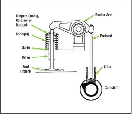
The term “valvetrain” refers to the mechanisms that cause a valve to function. There are several valvetrain designs and you may encounter cylinder heads with 2, 3, 4, or more valves per cylinder. Valves may operate individually or from a common bridge between valves. Whatever the design, all the components that make up the valvetrain can contribute to the performance, service life, and failure of a valve.
A broken part is often assumed to be the cause of the failure and during the repair of the engine the true cause may or may not be corrected. If it is not corrected, the cost and downtime for the second (or additional) repair will likely not be any less unpleasant than the first. Finding the real cause, the first time, can save a lot of headaches.
The greatest adversaries to a valve are misalignment, mis adjustment, debris, and heat. The best practice is to inspect the other valves and components. This will help determine if the problem is localized to just one cylinder, or if there are beginning stages of failure throughout the engine.
 .
. 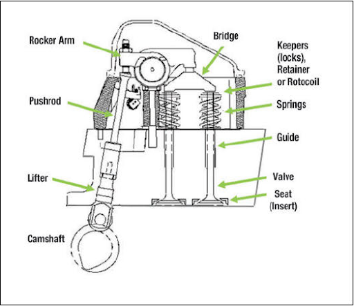
Some of the common terms and components are:
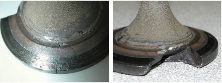 The head of the valve operates in the most severe conditions. It’s subjected to the most heat, and if operating conditions are not correct, it constantly slams shut against the seat. Chordal fatigue cracks in the valve head can develop due to the excessive temperature and/or overloading, as shown in the photos at the right. As the cracks advanced a piece of the valve head broke out.
 Most of a valve’s heat is transferred to the valve seat (insert). The remainder is cooled through the guide. Intake valves have the benefit of cool intake air passing them, exhaust valves obviously do not have that luxury.
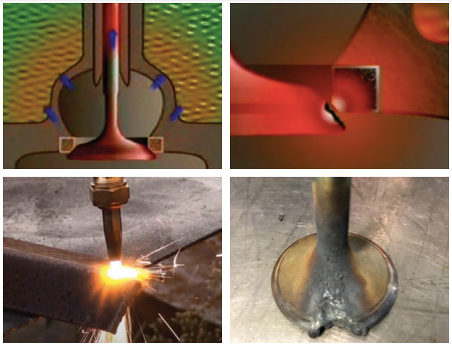
Anything that interferes with the valve’s ability to transfer heat can cause it to overheat and fail. If the valve is not sealing against the seat completely, hot combustion gas and compressing forces from the cylinder can pass between the valve and seat, working like a cutting torch melting the valve material.
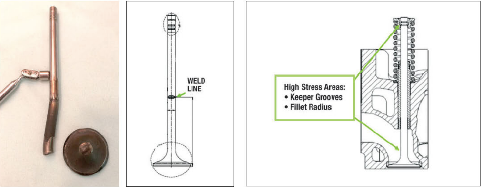
When a valve breaks in the fillet radius, one common misconception is that the weld failed. A simple test is to slide a magnet along the valve stem. This does not work on all valves due to the various valve designs and materials, but when it does it is likely you will find the weld line is considerably higher on the valve stem than expected. The weld line of the valve shown in the photo above is over 3 • (80mm) up from the valve face.
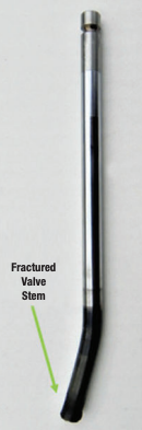
The fillet radius area of a valve is a high temperature and high load zone, and it is not a good place for a weld line. The most common cause for failure in this area is impact. Anything that causes the valve to stay open (debris, sticking in the guide, adjustment, etc.) can result in contact with the piston, and the valve is no match for the impact force from a piston.
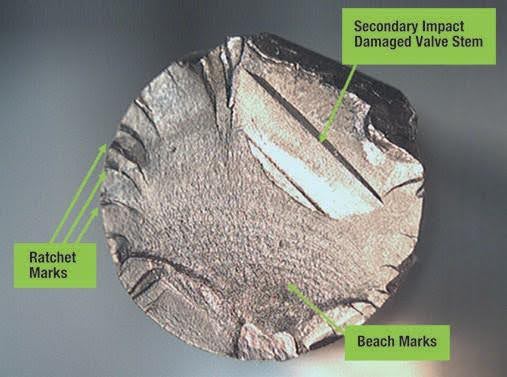
 Depending on the extent of secondary damage, the fractured surface of a broken valve stem can provide some vital information.
The surface of this valve stem has some tell-tale signs of the failure. Beach marks radiate out in a circular pattern from the initiation point. Beach marks widen as the fracture progresses. Ratchet marks indicate multiple crack initiation points from extreme stress. Since they initiate at different positions and levels they create steps in the fracture surface. This valve failed due to a fatigue fracture from the conditions it was subjected to, and not due to a defect.
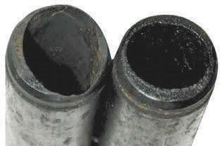
Inspecting the stem of the valve can tell a lot about the conditions the valve may have been operating in. Scoring on the stem and discoloration from heat are the two most often seen. Something as simple as extending the oil change (maintenance) can cause valves to stick. An open valve can also allow hot combustion gasses to coke(burn) the oil film in the guide. The cooking of oil means that it has become glass like and no longer aids in the transfer of heat and becomes an insulator. As the carbon build-up produced is very abrasive, coupled with its inability to transfer heat, the components wear quickly. Carbon and excessive wear are very visible in the photo of two valve guides shown here. The next question is if the guide is the cause or the result.
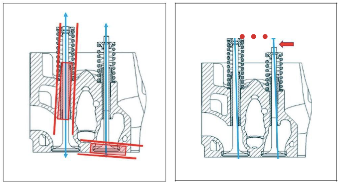
Incorrect alignment and adjustment can cause multiple problems. The guide must be concentric to the seat and the seat must be parallel to the guide. The related valve train components that create the valves’ movement must do so smoothly and cannot cause side loading of the valve. Misalignment can lead to premature wear, compression leaks, overheating, guttering, fatigue, and failure of any one of the valve components.
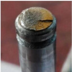
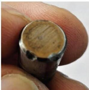
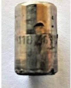
When a valve tip breaks, look for impact damage or side loading. Fretting between the keepers (lock) and the keeper grooves of the valve can result in fatigue fractures. Most valve train designs are intended for the valve to rotate. Rotating helps clean and evenly control the valve temperature. Inspecting the tip of the valve can indicate that the valve had been rotating and if the valve lash was too tight.
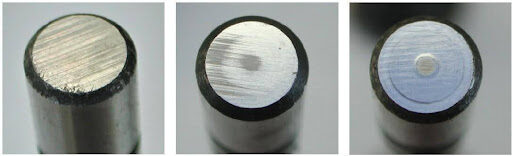
The valves below are all from the same engine, but the wear of the tips is obviously different. The tip on the left does not appear to have been rotating at all, the tip in the middle is starting to show a circular wear pattern. The tip of the right, by comparison, likely had little or no valve lash. The valve on the right is more prone to having deposits trapped on the sealing
surfaces between the valve and seat (insert). The valve of the right is more prone to be held slightly open and not allowed to seal properly. Either condition can cause a valve to overheat. Over time, most valves will develop the dimple in the center of the tip from normal wear. Comparing wear patterns between components is a good process to follow.
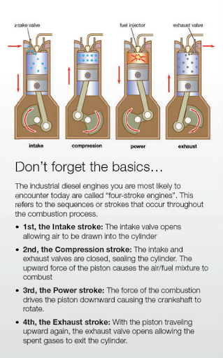
A four-stroke engine requires two revolutions of the crankshaft to complete one full cycle of the cylinders. At 2100 rpm each intake and exhaust valves open roughly 17 times per second. Valves are designed to withstand more than the normal operating conditions, but when something goes wrong or becomes too extreme, they take a beating very quickly.
As you can see there are many reasons for broken valves. The broken part may just be the messenger that can help lead you to what is or was really wrong. The best advice is to cure the cause, and not just treat the resulting symptoms.■

Steve Scott joined the service department at lPD in 1982, working with parts, service and sales for a variety of equipment, diesel, and natural gas engines. Since 2004, he has been the director of product development and technical support for lPD. For more information, email sscott@ipdparts.com.
If you’re an existing customer and already have a login, click here to find IPD quality parts.
If you would like to find an IPD distributor or become an IPD distributor, please fill out our form.